20-Meter
“J” Pole Vertical
By Mike Higgins, K6AER
During
what turned out to be an extended tower-raising project (Going from 55 feet to
90 feet), I had my beam down and I needed an antenna that could provide the necessary
gain and angle of radiation to talk to my friend Skip down at the South
Pole. A vertical would do the job but I
live on a ranch with horses and some times they get out of the corral. The
thought of having a bunch of radials where the horses might get tangled would
not be a big selling point with my wife.
These were her pets. Besides I had this vision of one of our horses
tangled in the radials just as the local TV crew happened by. Now I would have PETA, SPCA, FCC, the
building commission and who knows else banging at my door. Let’s not go there.
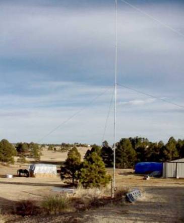
I finally decided, why not build a “J:” pole for 20 meters? No radials to mess
with, completely grounded and a low angle of radiation.
Construction
The “J” pole vertical is
built from a fifty-foot TV push up mast. You could use a tower section or
irrigation pipe. I had some push up masts available so I used one for the
antenna. In the case with the push up
mast you need to extend it out completely on the ground for measuring. That’s
when I found out a 50 foot TV push up mast is actually about 43 feet long. No problem, just add some lightweight
aluminum tubing to the last top section.
Basic construction of a
“J”-Pole antenna is for the top section to be ½ wave radiator with a ¼ wave
matching section for the feed. The
bottom of the feed section is actually a shorted ¼ wave autotransformer.
Impedance at the bottom of the antenna is very low. You can mount the base to a
wooden pole with no effect on performance.
Measure down from the top of the pole ½ wavelength for your desired
frequency. Using the formula 492/frequency (14.205 MHz), times the velocity
factor for a 2-inch pole (.97) gave me the length of 33 feet 7 inches. For the
matching section a quarter wavelength at my design frequency is 16 feet 9
inches. Mark the wavelength points with a felt marker so when you push up the
mast you can attach the proper hardware as you extend the mast.
The stand off for the top of
the quarter wave matching section is made from schedule 40 PVC. A 2 inch PVC “T” with a 1 inch side insert
that 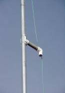 extends 7 inches is used to hold off the matching 12
gauge wire. The dielectric of PVC is more than sufficient to handle the
voltages with 1500 watts. If you were concerned with higher wattages you could
place a glass insulator at the top of the quarter wave wire matching section
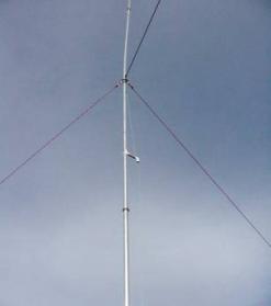
but I have found it unnecessary. The guy point rings for the TV mast were
removed except for the actual sections that would have the nylon rope attached.
This prevents lose metal pieces from rattling in the wind and causing
mechanical conduction static. The
antenna presents a very low wind loading and only need guying at the 30 and
40-foot sections. On the guy rings I attached the Nylon guy rope to small carabineer
clips and attached the clips to the guy rings. This prevents the guy rope from
fraying on the metal guy rings. The antenna has weathered 80 MPH winter ice and
blizzards with no ill effects.
extends 7 inches is used to hold off the matching 12
gauge wire. The dielectric of PVC is more than sufficient to handle the
voltages with 1500 watts. If you were concerned with higher wattages you could
place a glass insulator at the top of the quarter wave wire matching section
but I have found it unnecessary. The guy point rings for the TV mast were
removed except for the actual sections that would have the nylon rope attached.
This prevents lose metal pieces from rattling in the wind and causing
mechanical conduction static. The
antenna presents a very low wind loading and only need guying at the 30 and
40-foot sections. On the guy rings I attached the Nylon guy rope to small carabineer
clips and attached the clips to the guy rings. This prevents the guy rope from
fraying on the metal guy rings. The antenna has weathered 80 MPH winter ice and
blizzards with no ill effects.
The Big Push
The collapsed mast is
attached to the wooden pole. This will take the work out of raising the mast
until you can guy the antenna fully extended.
If you don’t mount the antenna to a post you will have to guy the mast
assembly at the10 foot point before raising the assembly.
And now some safety
guidelines. DO NOT ERRECT A TV PUSH UP MAST IF THE WIND IS OVER 5 MPH! DO NOT
ERRECT THE MAST ANYWHERE NEAR OVERHEAD VOLTAGE WIRES! Wear Leather Gloves.
 An
extended a TV push up mast is has cotter pins or bolts to prevent the sections
from sliding down should the setscrews become loosened. When erecting the mast
you fully extend each section and place the cotter pin or bolt into the mast to
prevent the upper section from slipping down to the lower section. After
setting the mast pin you rest the mast section on the pin and tighten the mast
section bolt. Repeat this procedure for each section.
An
extended a TV push up mast is has cotter pins or bolts to prevent the sections
from sliding down should the setscrews become loosened. When erecting the mast
you fully extend each section and place the cotter pin or bolt into the mast to
prevent the upper section from slipping down to the lower section. After
setting the mast pin you rest the mast section on the pin and tighten the mast
section bolt. Repeat this procedure for each section.
On a stable ladder
start extending the various sections starting with the smallest mast until you
get to the first guy point. Attach your 40-foot nylon guy ropes. Extend the
next section and attach the (30 ft.) guy ropes. Keep extending each section. At
the ½ wave point from the antenna top you attached the PVC standoff with hose
clamps. You can pre-make this assembly
including the matching 12-gauge wire before raising the mast. Extend each
section until the mast fully extended. Once the mast is fully erected set the
30-foot guys and then set the 40-foot guys. The hard part is over. Take a break
the mast is not going anywhere.
At the bottom end of the ¼ wave
matching wire you attach the end to the metal shorting bar and attach the bar
to the mast with a U bolt. The basic “J” pole is complete.
The Feed
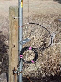 The feed and ten-turn choke balun was made from
LMR-400 low loss 50-Ohm cable. LMR-400 cable is made by Times Mirror
Corporation as is available for about $.43 a foot in 500-foot quantities. You can find suppliers in the back of QST
magazine. Loss at 14 MHz is about .45 dB. per 100 feet. To often I see hams put up a great antenna
only to throw away signal in a lossey piece of coax cable. The end of the cable
is attached with an “N” male connector. The feed point is connected with two
12-gauge wires soldered to an “N” female bulkhead connector. I use “N”
connectors for they are gasketed and you don’t have to worry about moisture
getting in the connector. The rear of the female connector is sealed with RTV
sealant. The center conductor is connected to the matching wire with a copper
ground split -bolt and the shield is connected to the mast with a cooper-grounding
strap. Attach the feed about 9 inches from the shorting bar. The base of the
antenna and shorting bar are grounded to a 10-foot ground rod.
The feed and ten-turn choke balun was made from
LMR-400 low loss 50-Ohm cable. LMR-400 cable is made by Times Mirror
Corporation as is available for about $.43 a foot in 500-foot quantities. You can find suppliers in the back of QST
magazine. Loss at 14 MHz is about .45 dB. per 100 feet. To often I see hams put up a great antenna
only to throw away signal in a lossey piece of coax cable. The end of the cable
is attached with an “N” male connector. The feed point is connected with two
12-gauge wires soldered to an “N” female bulkhead connector. I use “N”
connectors for they are gasketed and you don’t have to worry about moisture
getting in the connector. The rear of the female connector is sealed with RTV
sealant. The center conductor is connected to the matching wire with a copper
ground split -bolt and the shield is connected to the mast with a cooper-grounding
strap. Attach the feed about 9 inches from the shorting bar. The base of the
antenna and shorting bar are grounded to a 10-foot ground rod.
Adjustment
Using a VSWR Bridge or SWR
Analyzer adjust the feed points up or down until you match is flat at the
desired portion of the band. I have found the 2.0:1 VSWR to cover the whole 20
meter band with the 1.5:1 VSWR range covering from 14.100-14.310 MHz. VSWR
center point was set at 14.205 MHz.
On The Air
The antenna is very quiet.
The “J”-Pole is completely grounded. I live on the front range of Colorado and
the humidity is very low. We can have very high levels of “P” static. Lightning is a great concern during the
summer months and static build-up is a problem.
Before I started testing I placed
two reference dipoles at 40 feet with one strung north/south and the other
east/west. This was for comparing dipole to “J” pole signals over a two-week
period. Stations that were closer than
500 miles were consistently the same signal strength or one S-unit stronger on
the dipoles. This I attribute this to dipoles having a much higher angle of
radiation. Stations over 800 miles away were 1-2 S-units stronger with
international stations sometimes 3 S-units stronger. I can hear the critics
saying maybe it was the polarization arrival but in each case I could switch to
my horizontal reference dipoles each station on the band followed the distance
observation. Out of 200 stations
sampled over a 2-week period the results were always the same. On the air reports
consistently had contacts reporting an average of two S-units stronger signal
with the “J” pole when the distance was over 800 miles.
Proof In The Pudding
When hams talk of antenna
performance many quoted results of are antidotal. This basses of evaluation is
because they are not using reference antennas or performing proper antenna
modeling on an antenna range but empirically, “can I make contacts”. Well there is some truth in the old saying’
“can this dog hunt”. Alas the opportunity presented itself. A real test is how will the “J” pole antenna
work against the 20-meter mono banders during a worldwide DX contest?
About a month later I had my
chance and I was amazed. On a Saturday
in first week in March was the World Wide DX contest. You know the drill, S9+
noise level. Bottom line is I worked over 78 countries in six hours. Now I’m
not going to kid you that I was running 100 watts but my old TL-922 linear with
the “J” pole antenna would bust through the pileups and pull out a contact
within the second or third call 90% of the time. Each time I told the contact the antenna was a half wave “J” pole
they couldn’t believe the signal. Signal strength was generally within a S-unit
of the KW monobanders. Actual signal strength during a contest doesn’t mean
much. Each report is a higher layer of the liars club with some readings only
possible if the S-meter was wired to the power supply. What I was learning was not only of how fast
the contacts were coming but the relative difference from the Big Gun mono band
beam stations. My results from over 3 months of operation now have me listening
and calling CQ on the “J” pole first before switching to the beam. When the
band is quiet you just never know where it’s open to.
Variations
Versions of this antenna
could be made with matching sections for 10, 15, 17 and 20-meter portions
descending from the top of the antenna. This would be easiest using a Rohn 25
tower. Decoupling the different band coaxes would be accomplished by running
down the inside of the tower.
Building the antenna was
great fun and took about 4 hours from start to finish with only two trips to
the hardware store. Since building the antenna, several hams in the area has built
the 20-meter “J” pole to augment their DX antenna arrays. Contact surfing is a
lot easier than constantly rotating the beam and is a great antenna for round
robin rag chews. This is a perfect antenna for those who have limited yard
space. Best of all you can erect this by yourself with a little planning.
33’ 7” 16’ 9” ![]()
![]()
![]()
![]()
![]()
![]()
![]()
![]()
20 Meter “J”
All Grounded Vertical
Mike Higgins, K6AER Elizabeth, Colorado January 22, 2002
![]()
![]()

![]()
![]()
![]()
![]()
PVC Stand Off ![]()
![]() ¼ wave matching #12 ga. wire.
¼ wave matching #12 ga. wire.
9”
![]()
![]()
![]()
![]()
![]() Attach shield to main mast,
Attach shield to main mast,
 center conductor to matching
wire.

Shorting Bar LMR-400 50 Ohm
![]()
![]()
![]()

10 turns choke balun![]()
![]()
![]()
![]()
![]()
![]() Ground Mast
Ground Mast